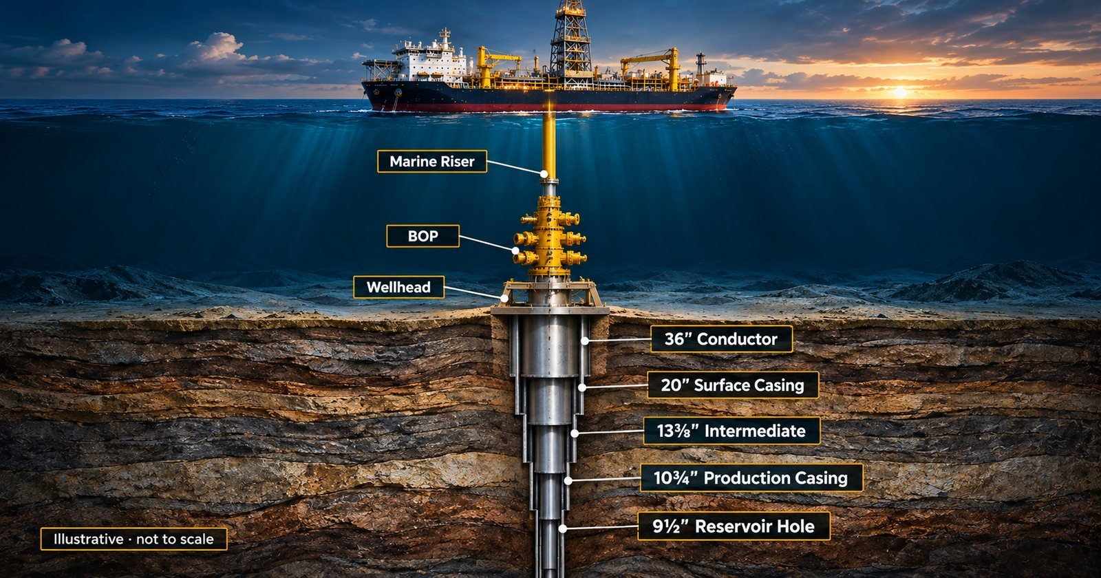
A deepwater well is built like a telescope pushed into the seabed. It starts wide and shallow, and every section that follows is narrower, deeper and less forgiving than the one before. Each string of casing exists for one reason: to protect what has been drilled so far, so the next section can be drilled safely.
Behind that telescope is a chain of engineering decisions. Which hole sizes to drill, where to set each casing shoe, what mud weight to carry, how to complete the reservoir: each choice is a trade-off between safety, cost and what the well must eventually deliver, and each one constrains the next.
This article walks through a representative deepwater well offshore Angola, from the moment the conductor goes into the mud to the day the well is handed over for production, and explains not only what is done in each section but why. The well architecture below is a representative composite built from publicly documented Angolan deepwater projects and general industry practice. Actual hole sizes, casing programmes, fluids, barriers and completion designs vary by field and well.
In this article
- Setting the scene: deepwater Angola
- Before the first metre: how the casing programme is planned
- 1. Spud and the 36″ conductor: building the foundation
- 2. The 26″ section: drilling without a riser
- 3. BOP and riser: the well gets a lid
- 4. The 17 1/2″ section: the intermediate interval
- 5. Hole enlargement: making room deeper in the well
- 6. The 9 1/2″ reservoir section: where the money is
- 7. Completion, clean-up and handover
- The well at a glance
- Key takeaways
- Sources
Setting the scene: deepwater Angola
Many of Angola’s established deepwater developments lie in the Lower Congo Basin, while major exploration and development also extend into the Kwanza Basin, where the Kaminho project on Block 20/11 is the first large-scale deepwater development (Offshore Magazine). TotalEnergies’ Kaombo project on Block 32 lies in roughly 1,400 to 1,950 m of water, about 260 km off Luanda, and needed 59 subsea wells tied back to two FPSOs through some 300 km of subsea lines (OGJ; TotalEnergies). Closer to shore, the Begonia development on Block 17/06 sits in 400 to 750 m of water, with five subsea wells tied back to the Pazflor FPSO (JPT).
The geology sets the rules for the drilling. Many of Angola’s deepwater reservoirs are weakly consolidated turbidite sands, making sand control a major completion requirement for producing wells (Staltari et al., SPE-178933-PA). The overburden can also contain reactive shale intervals, which influence drilling-fluid selection and often favour highly inhibitive systems (Whaley et al., SPE-107297-MS). Keep both facts in mind: they explain many of the choices further down the well.
Before the first metre: how the casing programme is planned
A central starting point in casing design is the pore-pressure and fracture-gradient (PPFG) profile plotted against depth. The pore pressure is the pressure of the fluids in the rock: if the pressure in the wellbore falls below it, formation fluids can flow into the well. The fracture gradient is the pressure at which the rock breaks: exceed it and the mud is lost into the formation. The space between the two curves is the drilling window. In conventional overbalanced drilling, the fluid system is designed to maintain sufficient bottomhole pressure to control formation pressure while staying below the formation’s fracture limit, with margins on both sides.
For a static fluid column of uniform density, the hydrostatic pressure at a given true vertical depth is, in field units:
Phyd (psi) = 0.052 × MW (ppg) × TVD (ft)For a step-by-step explanation with worked examples, see Hydrostatic Pressure and ECD: The Two Numbers Behind Every Mud Weight.
An open-hole section can only be drilled as long as one mud weight works for the whole interval. The mud needed to control pore pressure at the bottom of the section must remain below the fracture limit of the weakest exposed formation; for design purposes this is often associated with the previous casing shoe, but the weakest interval is not necessarily located there. When no single mud weight satisfies both limits, it is time to set casing. Pressure-window constraints are one of the primary drivers of casing setting depth, alongside geology, hazards and well objectives.
A second check is kick tolerance: the maximum design influx that can be circulated out without exceeding the allowable pressure at the weakest exposed formation, commonly evaluated at the previous casing shoe. If the planned section would leave too small a kick tolerance, the shoe has to go deeper or the section has to be shortened.
Casing sizes, on the other hand, are often worked out from the bottom up. The completion fixes the size of the reservoir hole: tubing, sand screens and the gravel-pack annulus all need room. Each casing string above must then pass through the one before it, with enough clearance to run it and cement it properly. Those constraints, worked upwards, are what produce the familiar sequence of sizes from the reservoir back to the conductor. Finally, every string is checked against the loads it will see during drilling, well control and production: burst, collapse and tension.
1. Spud and the 36″ conductor: building the foundation
The first string is often not drilled at all. In many soft-seabed deepwater settings, a large-diameter conductor, typically 36″, may be jetted into place: a bit and mud motor sit just below the conductor shoe, and the pipe is pushed into the sediment while fluid washes the soil away underneath it, without rotating the conductor itself (World Oil). Once at depth, the conductor is left to “soak” so the disturbed soil can grip it again before any weight is released (JPT). Depending on soil and design, conductors can also be driven, drilled and cemented, or installed through conductor-anchor systems (JPT).
In a typical architecture, the conductor carries the low-pressure wellhead housing and, later, much of the weight of everything hung on the well. Get it too short and it may not hold the axial load; jetting is so dependent on soil and crew that one supplier describes it as requiring “some art” (JPT).
Engineering focus. The conductor and surrounding soil form the structural foundation for the subsea wellhead system. Their axial capacity must support the relevant suspended loads, while structural design also accounts for bending generated by the BOP and riser system and by vessel motion. Because a jetted conductor depends on soil friction, its setting depth and soak time are engineering parameters, not operational details.
2. The 26″ section: drilling without a riser
The next section is drilled riserless. In a conventional deepwater top-hole sequence, this section is drilled before the marine riser and subsea BOP are installed, so there is no way to bring returns back to the rig. The well is drilled with seawater and viscous sweeps, or with “pump and dump” mud, and everything that comes out of the hole is released at the seabed (SPE PetroWiki, Riserless interval; Offshore Magazine).
This is where shallow hazards live: shallow water flow and shallow gas in young, unconsolidated sediments. Mitigation typically relies on detailed shallow-hazard surveys, careful well placement, contingency kill-fluid planning and continuous subsea observation where required. The section commonly ends with a surface casing string, often around 20″, supporting the high-pressure wellhead housing and cemented according to the well’s structural and barrier design.
The riserless phase can also be costly in time. Some case studies have shown that riserless operations can account for a disproportionate share of deepwater non-productive time (World Oil).
Engineering focus. The surface casing has two jobs: to isolate the shallow, unconsolidated sediments and any hazard zones before the BOP goes on, and to provide the first shoe strong enough for the mud weights of the next section. Its setting depth is a balance between a competent shoe and limiting how much hole is drilled without a BOP. With no returns at the rig, the team relies on subsea observation and downhole parameters to follow the well.
3. BOP and riser: the well gets a lid
With the 20″ casing and high-pressure housing in place, the rig runs the subsea BOP stack on the marine riser, joint by joint, down to the wellhead. In 1,500 m or more of water this is a long operation in its own right. Once the BOP is latched and pressure-tested, two things change for good.
- The well becomes a closed loop. Returns now travel up the riser to the rig, through the flowline to the shakers and back to the pits.
- Primary and secondary well control are both in place. Primary well control now relies on maintaining adequate hydrostatic pressure with the drilling fluid, while the BOP provides critical secondary well-control capability if formation fluids enter the wellbore.
Engineering focus. Deep water also introduces the concept of riser margin. If the riser mud column were lost or replaced by seawater, the hydrostatic contribution above the seabed would fall. Additional mud density can compensate for that loss where formation strength permits. In very deep water, however, the narrow pressure window may make a full riser margin impractical, so emergency-disconnect and BOP procedures are designed to maintain well control by other means.
4. The 17 1/2″ section: the intermediate interval
In many conventional deepwater well designs, the 17 1/2″ interval forms a substantial intermediate section, drilled through thick shale sequences towards the top of the reservoir interval. It usually ends with an intermediate casing string, commonly 13 3/8″, set deep enough to give the next section a strong shoe.
Synthetic-based muds are commonly used in deepwater wells for intervals where shale inhibition, hole stability and rheological control are critical, although fluid selection remains a field-specific engineering decision. The mud weight has to sit inside a window: heavy enough to hold back formation pressure and keep the shales stable, light enough not to fracture the rock. In deep water, the large water column contributes less overburden stress than an equivalent thickness of sediment, which can reduce shallow fracture gradients and narrow the operating window.
Engineering focus. The 13 3/8″ shoe depth is planned before the section is drilled, from the PPFG profile, the geology and kick tolerance. After drilling out the previous shoe, a formation integrity test (FIT) may confirm that the formation can withstand a predetermined design pressure, while a leak-off test (LOT) can be continued until leakoff is observed to estimate the formation’s pressure limit. The demonstrated shoe integrity or LOT result then helps define the allowable pressure envelope for the section, with an appropriate operating margin. While drilling, cavings, increasing torque and drag, or recurrent tight spots can indicate deteriorating hole condition and must be interpreted alongside cuttings morphology, hydraulics and other drilling data before adjusting mud weight.
5. Hole enlargement: making room deeper in the well
In some well designs, a 12 1/4″ bit drills a pilot hole, and a reamer higher up in the bottomhole assembly opens it to 13 1/2″ while drilling. Why not just drill a bigger hole? Because the bit has to pass through the casing above it. Hole enlargement while drilling is the trick that lets the well keep a larger casing size deeper down, with enough clearance to run the string and to get a good cement job around it (Offshore Magazine). On Girassol in Block 17, for example, the operator preferred 10 3/4″ production casing above the reservoir hole to gain annular clearance for the sand screens (Offshore Magazine). It is a clear example of bottom-up design: a completion requirement at the bottom of the well sets the casing size several sections higher.
By this depth the operating window may also be tighter, which makes ECD management especially important. This section often approaches the reservoir, where the margin between pore pressure and fracture pressure is frequently at its narrowest. Equivalent circulating density (ECD), the effective mud weight felt by the formation while pumping, has to be managed constantly: too low and the well can flow, too high and the formation breaks down and the mud disappears into it. In field units, ECD at a given depth adds the annular friction pressure loss down to that depth to the static mud weight, with TVD taken at the same point:
ECD (ppg) = MW (ppg) + ΔPann (psi) / [0.052 × TVD (ft)]Engineering focus. ECD is managed with hydraulics models before and during drilling. Flow rate, rotary speed and rate of penetration are chosen to clean the hole without overloading the annulus with cuttings, and tripping speeds are limited to control swab and surge pressures. Pressure-while-drilling measurements provide annular pressure near the downhole tool, allowing the hydraulics model and ECD estimate to be checked against real-time measurements.
6. The 9 1/2″ reservoir section: where the money is
The last hole section goes into the reservoir itself, often as a 9 1/2″ hole below the production casing, a geometry described publicly for Block 17 (Offshore Magazine). The priorities change here. Until now the goal was to reach depth safely; now it is also to protect the rock that will produce.
- Formation damage. The drilling fluid is often conditioned or replaced with a reservoir drill-in fluid designed to be cleaned up later, because whatever invades the sand can reduce how much the well will deliver.
- Trajectory. Many producers are high-angle or horizontal, steered with logging-while-drilling tools to stay inside the best sand.
- Well control. The well is now open to hydrocarbon-bearing formations, so kick detection matters more than ever.
Engineering focus. In the reservoir, decisions are made in real time from several data streams. Logging-while-drilling tools show where the bit sits in the sand, pressure-while-drilling confirms the ECD, and surface monitoring adds early evidence of what the well is doing: gas readings, cuttings, pit volumes and return flow. Gas shows help identify hydrocarbon-bearing intervals and support correlation of the reservoir top when interpreted alongside cuttings, drilling parameters and LWD data (SLB, Defining Mud Logging). A drilling break followed, after the appropriate lag, by an abnormal gas increase warrants immediate attention; depending on the circumstances and operating procedure, the team may need to verify that the well is static before treating the response simply as a reservoir show.
7. Completion, clean-up and handover
Drilling ends at total depth, but the well is not a producer yet. Because the sands are weak, the lower completion has to keep them in place. One of the most widely used solutions for deepwater producers in Angola is the openhole gravel pack: screens run across the reservoir, with the annulus between screen and rock packed with gravel (Staltari et al., SPE-178933-PA). On Kaombo, operators used openhole gravel packs with mechanical packers to isolate unwanted layers while producing several stacked reservoirs through one well (SLB, SPE 189491).
A simplified completion sequence might look like this:
- Displacement. The open hole is displaced from drilling fluid to a clean completion fluid, so the screens and gravel pack are not plugged.
- Lower completion. Screens and gravel pack, or a frac pack in some cased-hole wells.
- Upper completion. Production tubing, subsurface safety valve and permanent downhole gauges are installed, with the tubing suspended from the tubing-hanger and wellhead system; the exact sequence depends on the subsea-tree architecture.
- Clean-up and well test. The well is flowed to remove completion fluids and debris and to confirm its productivity.
- Handover. The completed well is then secured and handed over for the next stage of subsea integration and production or injection operations.
Engineering focus. The completion is where the logic of the whole well closes. The screen and gravel-pack design set the size of the reservoir hole, which in turn influences the production casing and the diameters above it. The well’s diameter architecture is often worked backwards from the completion requirements, while casing setting depths are constrained by the geology and pressure window encountered from the top down. The well is then physically drilled from the conductor toward the reservoir.
The well at a glance
| Section | Typical string | Main concern | Key engineering decision |
|---|---|---|---|
| 36″ (often jetted) | 36″ conductor | Foundation strength | Setting depth and soil capacity; structural resistance to axial and bending loads |
| 26″ (riserless) | Surface casing (often 20″) and HP housing | Shallow water flow and gas | Shoe depth: competent shoe versus hole drilled without a BOP |
| 17 1/2″ | 13 3/8″ casing | Shale stability, pressure window | Mud weight inside the window; shoe depth from PPFG, geology and kick tolerance; post-drillout integrity verified by FIT/LOT |
| Enlarged section (e.g. 12 1/4″ x 13 1/2″) | Production casing (e.g. 10 3/4″) | ECD and losses | Hole enlargement for casing clearance; ECD management |
| 9 1/2″ reservoir | Sand-control completion | Formation damage, kicks | Drill-in fluid, trajectory and a completion-ready hole |
Key takeaways
- A deepwater well is a sequence of trade-offs: every casing string buys safety for the next section and costs diameter for the rest of the well.
- Casing setting depths are driven by the pressure window, geology, hazards and kick tolerance; casing diameters are often worked out from the completion upwards.
- The riserless sections combine limited return monitoring with shallow-hazard exposure and can be operationally demanding.
- Deeper down, the narrow window between pore and fracture pressure drives almost every decision, from mud weight to hole enlargement.
- Real-time data, downhole and at surface, is what tells the team whether the well still matches the plan.
The views in this article are my own and are based on public sources and general industry practice. They do not describe any specific well or represent any current or former employer.
Sources
- TotalEnergies. Kaombo: An Innovative Ultra-Deep-Water Offshore Project in Angola. totalenergies.com
- Oil & Gas Journal (2 April 2019). Total begins full-field production on Kaombo with second FPSO. ogj.com
- JPT (2025). TotalEnergies Boosts Offshore Angola Production by 60,000 BOPD (Begonia and CLOV Phase 3). jpt.spe.org
- Offshore Magazine (21 May 2024). TotalEnergies launches Kaminho oil project offshore Angola. offshore-mag.com
- Staltari, D., Urdaneta, J., Pellicanò, D., Ripa, G., Cauende, C., Parlar, M. et al. (2017). A Deepwater Openhole Gravel Pack Completion With Prolonged Well Suspension Without Initial Cleanup: An Angola Block 15/06 Case History. SPE Drilling & Completion 32: 79-85. SPE-178933-PA. DOI: 10.2118/178933-PA
- Whaley, K.S., Price-Smith, C.J., Twynam, A.J. and Jackson, P.J. (2007). Greater Plutonio Open Hole Gravel Pack Completions: Fluid Design and Field Application. SPE-107297-MS. DOI: 10.2118/107297-MS
- SPE 189491 (2018). Openhole Mechanical Packer With Eccentric Shunt-Tube Gravel Pack Assembly Reduces Capex and Accelerates Production in Kaombo Deepwater Development, Angola. Summary: SLB case study
- Varhaug, M. (2015). The Defining Series: Mud Logging. Oilfield Review, SLB. slb.com
- SPE PetroWiki. Riserless interval. petrowiki.spe.org
- Offshore Magazine (June 2001). Riserless drilling: Advances in riserless drilling pushing the deepwater surface string envelope. offshore-mag.com
- World Oil (August 2023). Riserless casing drilling technology for the deepwater top hole. read.nxtbook.com
- JPT (2017). Conductor Anchor Node Optimizes Efficiency of Riserless Deepwater Exploration Drilling. jpt.spe.org
- JPT. Conductor Anchor Node Adds Stability, Cuts Tophole Costs in Subsea Wells. pubs.spe.org
- Offshore Magazine. Near-bit reaming tool allows continuous drilling, under-reaming. offshore-mag.com
- Offshore Magazine. Cased-hole sand-control completions work well in wells off Angola (Girassol). offshore-mag.com